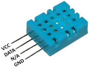
STM32操纵DHT11湿度传感器
网上的例子不是说不能用,而是各种坑爹引用,搞得想移植都要改半天。现贴出一份经过Sandeepin精心整理的、清晰明了的代码供大家直观学习。
其实DHT11传感器不仅可测湿度,温度也能测,所以代码中包括了两种数据。
不多废话,直接上代码:
#include "stm32f10x.h"

#include "stdio.h"


#define HIGH  1

#define LOW   0

#define DHT11_CLK     RCC_APB2Periph_GPIOC

#define DHT11_PIN     GPIO_Pin_2

#define DHT11_PORT    GPIOC

#define DHT11_DATA_IN()   GPIO_ReadInputDataBit(GPIOC,GPIO_Pin_2) //读取引脚的电平

//带参宏,可以像内联函数一样使用,输出高电平或低电平

#define DHT11_DATA_OUT(a)  if (a)  \

                    GPIO_SetBits(GPIOC,GPIO_Pin_2);\

                    else        \

                    GPIO_ResetBits(GPIOC,GPIO_Pin_2)


u32 TimingDelay;


typedef struct

{

    uint8_t  humi_int;  //湿度的整数部分

    uint8_t  humi_deci; //湿度的小数部分

    uint8_t  temp_int;  //温度的整数部分

    uint8_t  temp_deci; //温度的小数部分

    uint8_t  check_sum; //校验和

}DHT11_Data_TypeDef;


void Delay_us(u32 ntimes)

{

    u32 flag;

    SysTick->LOAD=9*ntimes; //时间加载

    SysTick->VAL=0; //清空计数器

    SysTick->CTRL=0x00000001; //bit2清空,选择外部时钟HCLK/8, bit0位清空,开启倒计时

    do

    {

        flag=SysTick->CTRL;

    }

    while(flag&0x01&&!(flag&(1<<16)));//等待时间到达

    SysTick->CTRL=0;//关闭计数器

}


int fputc(int ch, FILE *f)//重定向c库函数printf到USART1

{

    USART_SendData(USART1, (unsigned char) ch);//将Printf内容发往串口

    while( USART_GetFlagStatus(USART1,USART_FLAG_TC)!= SET);

    return (ch);

}


void USART1_Config(unsigned int bound)

{

    GPIO_InitTypeDef GPIO_InitStructure;

    USART_InitTypeDef USART_InitStructure;

    RCC_APB2PeriphClockCmd(RCC_APB2Periph_USART1 | RCC_APB2Periph_GPIOA, ENABLE);

    GPIO_InitStructure.GPIO_Pin = GPIO_Pin_9;

    GPIO_InitStructure.GPIO_Mode = GPIO_Mode_AF_PP;

    GPIO_InitStructure.GPIO_Speed = GPIO_Speed_50MHz;

    GPIO_Init(GPIOA, &GPIO_InitStructure);

    GPIO_InitStructure.GPIO_Pin = GPIO_Pin_10;

    GPIO_InitStructure.GPIO_Mode = GPIO_Mode_IN_FLOATING;

    GPIO_Init(GPIOA, &GPIO_InitStructure);

    USART_InitStructure.USART_BaudRate = bound;

    USART_InitStructure.USART_WordLength = USART_WordLength_8b;

    USART_InitStructure.USART_StopBits = USART_StopBits_1;

    USART_InitStructure.USART_Parity = USART_Parity_No;

    USART_InitStructure.USART_HardwareFlowControl = USART_HardwareFlowControl_None;

    USART_InitStructure.USART_Mode = USART_Mode_Rx | USART_Mode_Tx;

    USART_Init(USART1, &USART_InitStructure);

    USART_Cmd(USART1, ENABLE);

}


void DHT11_GPIO_Config(void)//DHT11的GPIO配置

{

    GPIO_InitTypeDef GPIO_InitStructure;

    RCC_APB2PeriphClockCmd(DHT11_CLK, ENABLE);

    GPIO_InitStructure.GPIO_Pin = DHT11_PIN;

    GPIO_InitStructure.GPIO_Mode = GPIO_Mode_Out_PP;

    GPIO_InitStructure.GPIO_Speed = GPIO_Speed_50MHz;

    GPIO_Init(DHT11_PORT, &GPIO_InitStructure);

    GPIO_ResetBits(DHT11_PORT, GPIO_Pin_2);

}


static void DHT11_Mode_IPU(void)//使DHT11-DATA引脚变为上拉输入模式

{

    GPIO_InitTypeDef GPIO_InitStructure;

    GPIO_InitStructure.GPIO_Pin = DHT11_PIN;

    GPIO_InitStructure.GPIO_Mode = GPIO_Mode_IPU;

    GPIO_Init(DHT11_PORT, &GPIO_InitStructure);

}


static void DHT11_Mode_Out_PP(void)//使DHT11-DATA引脚变为推挽输出模式

{

    GPIO_InitTypeDef GPIO_InitStructure;

    GPIO_InitStructure.GPIO_Pin = DHT11_PIN;

    GPIO_InitStructure.GPIO_Mode = GPIO_Mode_Out_PP;

    GPIO_InitStructure.GPIO_Speed = GPIO_Speed_50MHz;

    GPIO_Init(DHT11_PORT, &GPIO_InitStructure);

}


static uint8_t Read_Byte(void)//从DHT11读取一个字节,MSB先行

{

    uint8_t i, temp=0;

    for(i=0;i<8;i++)

    {

        while(DHT11_DATA_IN()==Bit_RESET);//每bit以50us低电平标置开始,轮询直到从机发出 的50us 低电平 结束

        //DHT11 以26~28us的高电平表示“0”,以70us高电平表示“1”,

        //通过检测 x us后的电平即可区别这两个状 ,x 即下面的延时

        Delay_us(40); //延时x us 这个延时需要大于数据0持续的时间即可

        if(DHT11_DATA_IN()==Bit_SET)// x us后仍为高电平表示数据“1”

        {

            while(DHT11_DATA_IN()==Bit_SET);//等待数据1的高电平结束

            temp|=(uint8_t)(0x01<<(7-i));  //把第7-i位置1,MSB先行

        }

        else     // x us后为低电平表示数据“0”

        {

            temp&=(uint8_t)~(0x01<<(7-i)); //把第7-i位置0,MSB先行

        }

    }

    return temp;

}


uint8_t Read_DHT11(DHT11_Data_TypeDef *DHT11_Data)//一次完整的数据传输为40bit,高位先出,8bit 湿度整数 + 8bit 湿度小数 + 8bit 温度整数 + 8bit 温度小数 + 8bit 校验和

{

    DHT11_Mode_Out_PP();


    DHT11_DATA_OUT(LOW);//主机拉低

    Delay_us(18000);//延时18ms

    DHT11_DATA_OUT(HIGH); //总线拉高 主机延时30us

    Delay_us(30);   //延时30us

    DHT11_Mode_IPU();//主机设为输入 判断从机响应信号

    if(DHT11_DATA_IN()==Bit_RESET)//判断从机是否有低电平响应信号 如不响应则跳出,响应则向下运行

    {

        while(DHT11_DATA_IN()==Bit_RESET);//轮询直到从机发出 的80us 低电平响应信号结束

        while(DHT11_DATA_IN()==Bit_SET);//轮询直到从机发出的 80us 高电平 标置信号结束

        DHT11_Data->humi_int= Read_Byte();//开始接收数据

        DHT11_Data->humi_deci= Read_Byte();

        DHT11_Data->temp_int= Read_Byte();

        DHT11_Data->temp_deci= Read_Byte();

        DHT11_Data->check_sum= Read_Byte();

        DHT11_Mode_Out_PP();//读取结束,引脚改为输出模式

        DHT11_DATA_OUT(HIGH);//主机拉高

        //检查读取的数据是否正确

        if(DHT11_Data->check_sum == DHT11_Data->humi_int + DHT11_Data->humi_deci + DHT11_Data->temp_int+ DHT11_Data->temp_deci)

            return SUCCESS;

        else

            return ERROR;

    }

    else

    {

        return ERROR;

    }

}


DHT11_Data_TypeDef DHT11_Data;

int main(void)

{

    USART1_Config(9600);

    DHT11_GPIO_Config();

    while(1){//调用Read_DHT11读取温湿度,若成功则输出该信息

        if( Read_DHT11(&DHT11_Data)==SUCCESS)

        {

            printf("Relative Humidity: %d.%d  Temperature: %d.%d \r\n",\

                DHT11_Data.humi_int,DHT11_Data.humi_deci,DHT11_Data.temp_int,DHT11_Data.temp_deci);

            Delay_us(500000);

        }

        else

        {

            printf("Read DHT11 ERROR! \r\n");

            Delay_us(500000);

        }

    }

}
实现效果:在PC2接湿度传感器,通过串口1打印出湿度值、温度值。