STM32学习笔记:基础例子
本例子代码参考了STM32库开发实战指南中的代码,由于使用的板子是尚学STM32F103ZET6,为了配合板上已有资源,也参考了其配套代码。为了便于书写文本,我尽量将代码都写到了一个文件中,这种方式是不推荐的,在做具体工程时最好代码分类管理,使工程逻辑清晰。
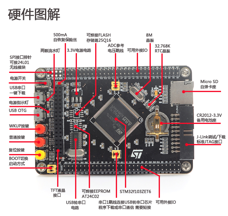
现在对板上一些资源说明:板上有两个LED灯,引脚为PE5、PE6,均为ResetBits时点亮。有三个按钮,依次为黄色复位,红色PE4(按下接GND)、红色PA0(按下接3.3V,WAKE UP按钮)。ISP口为靠近电源开关的USB,也是USART1口。USART2口为PA3(Rx)、PA2(Tx)。IPD为高电平中断(按键一边接高电平),IPU为低电平中断。
接下来例举基本操作:
用GPIO点亮灯(GPIO输出)
#include "stm32f10x.h"

void Delay(__IO u32 nCount)  //简单的延时函数

{

    for(; nCount != 0; nCount--);

}


void GPIO_Config(void) //配置LED用到的I/O口

{

    GPIO_InitTypeDef GPIO_InitStructure; //定义一个GPIO_InitTypeDef类型的结构体

    RCC_APB2PeriphClockCmd( RCC_APB2Periph_GPIOE, ENABLE); //开启GPIOE的外设时钟

    GPIO_InitStructure.GPIO_Pin = GPIO_Pin_5 | GPIO_Pin_6; //选择要控制的GPIOE引脚,这里选了PE5、PE6

    GPIO_InitStructure.GPIO_Mode = GPIO_Mode_Out_PP; //设置引脚模式为:通用推挽输出

    GPIO_InitStructure.GPIO_Speed = GPIO_Speed_50MHz; //设置引脚速率为:50MHz

    GPIO_Init(GPIOE, &GPIO_InitStructure);  //调用库函数,初始化GPIOE

    GPIO_SetBits(GPIOE, GPIO_Pin_5 | GPIO_Pin_6); //关闭所有LED灯

}


int main(void)

{

    GPIO_Config();

    while(1)

    {

    GPIO_SetBits(GPIOE , GPIO_Pin_5); //PE5输出高电平

    GPIO_ResetBits(GPIOE,GPIO_Pin_6); //PE6输出低电平

    Delay(1000000);//1,000,000 六个零以上才有明显闪烁

    GPIO_SetBits(GPIOE , GPIO_Pin_6); //PE6输出高电平

    GPIO_ResetBits(GPIOE,GPIO_Pin_5); //PE5输出低电平

    Delay(1000000);

    }

}
实现效果:PE6、PE5两盏灯闪烁。
按键输入(GPIO输入)
#include "stm32f10x.h"

#define KEY1 GPIO_ReadInputDataBit(GPIOE,GPIO_Pin_4)   //读PE4(GND)

#define KEY2 GPIO_ReadInputDataBit(GPIOA,GPIO_Pin_0)   //读PA0(VCC)


void Delay(__IO u32 nCount)  //简单的延时函数

{

    for(; nCount != 0; nCount--);

}


void GPIO_Config(void) //配置LED用到的PE5、PE6

{

    GPIO_InitTypeDef GPIO_InitStructure; //定义一个GPIO_InitTypeDef类型的结构体

    RCC_APB2PeriphClockCmd( RCC_APB2Periph_GPIOE, ENABLE); //开启GPIOE的外设时钟

    GPIO_InitStructure.GPIO_Pin = GPIO_Pin_5 | GPIO_Pin_6; //选择要控制的GPIOE引脚,这里选了PE5、PE6

    GPIO_InitStructure.GPIO_Mode = GPIO_Mode_Out_PP; //设置引脚模式为:通用推挽输出

    GPIO_InitStructure.GPIO_Speed = GPIO_Speed_50MHz; //设置引脚速率为:50MHz

    GPIO_Init(GPIOE, &GPIO_InitStructure);  //调用库函数,初始化GPIOE

    GPIO_SetBits(GPIOE, GPIO_Pin_5 | GPIO_Pin_6); //关闭所有LED灯

}


void Key_GPIO_Config(void)//按键配置,这里用PE4、PE5输入

{

    GPIO_InitTypeDef GPIO_InitStructure;

    RCC_APB2PeriphClockCmd(RCC_APB2Periph_GPIOE,ENABLE);//开启GPIOE的时钟

    GPIO_InitStructure.GPIO_Pin = GPIO_Pin_4; //设置引脚PE4

    GPIO_InitStructure.GPIO_Mode = GPIO_Mode_IPU; //上拉输入模式(按键按下接GND用这个)

    GPIO_Init(GPIOE, &GPIO_InitStructure);


    RCC_APB2PeriphClockCmd(RCC_APB2Periph_GPIOA,ENABLE);

    GPIO_InitStructure.GPIO_Pin  = GPIO_Pin_0;

    GPIO_InitStructure.GPIO_Mode = GPIO_Mode_IPD; //下拉输入模式(按键按下接VCC用这个)

    GPIO_Init(GPIOA, &GPIO_InitStructure);

}


unsigned char KEY1_Scan(void)

{

    static char key_up0=0;//按键按松开标志

    if(KEY1==0)

    {

    Delay(10000);//延时去抖动

        if(KEY1==0)

        {

            key_up0=1;

        }


    }

    if(KEY1==1&&key_up0==1)

    {

    key_up0=0;

    return 1;

    }

    return 0;

}


unsigned char KEY2_Scan(void)

{

    static char key_up2=0;//按键按松开标志

    if(KEY2==1)

    {

    Delay(10000);//延时去抖动

        if(KEY2==1)

        {

            key_up2=1;

        }

    }

    if(KEY2==0&&key_up2==1)

    {

        key_up2=0;

        return 1;

    }

    return 0;

}


unsigned char KEY_Scan(void)

{

    unsigned char key_code;

    if(KEY1_Scan()==1) key_code=1;

    else if(KEY2_Scan()==1) key_code=2;

    else key_code=0;

    return key_code;

}


int main(void)

{

    int value=0;

    GPIO_Config();

    Key_GPIO_Config();//配置按键

    while(1)

    {

        value=KEY_Scan();//获取按键值

        if(value==1)

        GPIO_WriteBit(GPIOE, GPIO_Pin_5, (BitAction)(1-(GPIO_ReadOutputDataBit(GPIOE, GPIO_Pin_5))));//LED灯PE5反转

        else if(value==2)

        GPIO_WriteBit(GPIOE, GPIO_Pin_6, (BitAction)(1-(GPIO_ReadOutputDataBit(GPIOE, GPIO_Pin_6))));//LED灯PE6反转

    }

}
实现效果:PE4按下控制PE5灯反转,PA0按下控制PE6灯反转(亮、灭)。
按键中断(EXTI外部中断操作)
#include "stm32f10x.h"

void Delay(__IO u32 nCount)  //简单的延时函数

{

    for(; nCount != 0; nCount--);

}


void GPIO_Config(void) //配置LED用到的PE5、PE6

{

    GPIO_InitTypeDef GPIO_InitStructure; //定义一个GPIO_InitTypeDef类型的结构体

    RCC_APB2PeriphClockCmd( RCC_APB2Periph_GPIOE, ENABLE); //开启GPIOE的外设时钟

    GPIO_InitStructure.GPIO_Pin = GPIO_Pin_5 | GPIO_Pin_6; //选择要控制的GPIOE引脚,这里选了PE5、PE6

    GPIO_InitStructure.GPIO_Mode = GPIO_Mode_Out_PP; //设置引脚模式为:通用推挽输出

    GPIO_InitStructure.GPIO_Speed = GPIO_Speed_50MHz; //设置引脚速率为:50MHz

    GPIO_Init(GPIOE, &GPIO_InitStructure);  //调用库函数,初始化GPIOE

    GPIO_SetBits(GPIOE, GPIO_Pin_5 | GPIO_Pin_6); //关闭所有LED灯

}


static void NVIC_Configuration(void)//NVIC(中断控制器)初始化配置,这里配PE4、PA0

{

    NVIC_InitTypeDef NVIC_InitStructure;

    NVIC_PriorityGroupConfig(NVIC_PriorityGroup_1);//把NVIC中断优先级分组设为第1组

    NVIC_InitStructure.NVIC_IRQChannel = EXTI4_IRQn;//PE4对应EXTI线为EXTI4,填EXTI4_IRQn。(EXTI5~EXTI9使用同一中断向量,则填EXTI9_5_IRQn)

    NVIC_InitStructure.NVIC_IRQChannelPreemptionPriority = 2;//抢占优先级2

    NVIC_InitStructure.NVIC_IRQChannelSubPriority = 1;//响应优先级1

    NVIC_InitStructure.NVIC_IRQChannelCmd = ENABLE;

    NVIC_Init(&NVIC_InitStructure);//向寄存器写入参数


    NVIC_InitStructure.NVIC_IRQChannel = EXTI0_IRQn;//PA0对应EXTI线为EXTI0,填EXTI0_IRQn

    NVIC_InitStructure.NVIC_IRQChannelPreemptionPriority = 2;//抢占优先级2

    NVIC_InitStructure.NVIC_IRQChannelSubPriority = 2;//响应优先级2

    NVIC_InitStructure.NVIC_IRQChannelCmd = ENABLE;//IRQ(中断请求)通道使能

    NVIC_Init(&NVIC_InitStructure);//向寄存器写入参数

}


void EXTI_Config(void)//配置PE4、PA0为线中断口,并设置中断优先级

{

    GPIO_InitTypeDef GPIO_InitStructure;

    EXTI_InitTypeDef EXTI_InitStructure;

    RCC_APB2PeriphClockCmd(RCC_APB2Periph_GPIOA | RCC_APB2Periph_AFIO,ENABLE);//配置中断线(PA0)时钟和第二功能AFIO时钟,AFIO指GPIO口的复用功能

    RCC_APB2PeriphClockCmd(RCC_APB2Periph_GPIOE | RCC_APB2Periph_AFIO,ENABLE);//配置中断线(PE4)时钟和第二功能AFIO时钟


    NVIC_Configuration();//配置NVIC中断控制器


    //以下配PE4

    GPIO_InitStructure.GPIO_Pin = GPIO_Pin_4; //选定要配置为EXTI线的gpio口和设置其工作模式

    GPIO_InitStructure.GPIO_Mode = GPIO_Mode_IPU;//上拉输入

    GPIO_Init(GPIOE, &GPIO_InitStructure);

    //以下配PA0

    GPIO_InitStructure.GPIO_Pin  = GPIO_Pin_0;//选PA0

    GPIO_InitStructure.GPIO_Mode = GPIO_Mode_IPD;//下拉输入

    GPIO_Init(GPIOA, &GPIO_InitStructure);

    //以下配PE4中断线、初始化配置

    GPIO_EXTILineConfig(GPIO_PortSourceGPIOE, GPIO_PinSource4); //EXTI中断线(PE5)工作模式配置

    EXTI_InitStructure.EXTI_Line = EXTI_Line4;

    EXTI_InitStructure.EXTI_Mode = EXTI_Mode_Interrupt;

    EXTI_InitStructure.EXTI_Trigger = EXTI_Trigger_Falling; //下降沿中断

    EXTI_InitStructure.EXTI_LineCmd = ENABLE;

    EXTI_Init(&EXTI_InitStructure);

    //以下配PA0中断线、初始化配置

    GPIO_EXTILineConfig(GPIO_PortSourceGPIOA, GPIO_PinSource0); //EXTI中断线(PA0)工作模式配置

    EXTI_InitStructure.EXTI_Line = EXTI_Line0;

    EXTI_InitStructure.EXTI_Mode = EXTI_Mode_Interrupt;

    EXTI_InitStructure.EXTI_Trigger = EXTI_Trigger_Rising; //上升沿中断

    EXTI_InitStructure.EXTI_LineCmd = ENABLE;

    EXTI_Init(&EXTI_InitStructure);

}


int main(void)

{

    GPIO_Config();//LED(PE5、PE6)配置

    EXTI_Config(); //外部中断EXTI配置,这里是选PE4、PA0

    while(1)//等待中断

    {

    }

}
在stm32f10x_it.c中加入名为EXTI0_IRQHandler(void)和EXTI4_IRQHandler(void)函数:
void EXTI0_IRQHandler(void)

{

    Delay(10000);//延时消抖

    if(EXTI_GetITStatus(EXTI_Line0) != RESET)//检查指定的EXTI0线路触发请求发生与否

    {

        GPIO_WriteBit(GPIOE, GPIO_Pin_6, (BitAction)(1-(GPIO_ReadOutputDataBit(GPIOE, GPIO_Pin_6))));//控制LED的PE6翻转

    }

    EXTI_ClearITPendingBit(EXTI_Line0);//清除EXTI0线路挂起位

}


void EXTI4_IRQHandler(void)

{

    Delay(10000);//延时消抖

    if(EXTI_GetITStatus(EXTI_Line4) != RESET)//确保是否产生了EXTI4 Line中断

    {

        GPIO_WriteBit(GPIOE, GPIO_Pin_5, (BitAction)(1-(GPIO_ReadOutputDataBit(GPIOE, GPIO_Pin_5))));//控制LED的PE5翻转

    }

    EXTI_ClearITPendingBit(EXTI_Line4);//清除中断标志位

}
实现效果:PE4按下触发中断,控制PE5灯反转;PA0按下触发中断,控制PE6灯反转(亮、灭)。
串口打印(用USART1)
#include "stm32f10x.h"

#include "stdio.h"

void Delay(__IO u32 nCount)  //简单的延时函数

{

    for(; nCount != 0; nCount--);

}


int fputc(int ch, FILE *f)//重定向c库函数printf到USART1

{

    USART_SendData(USART1, (unsigned char) ch);//将Printf内容发往串口

    while( USART_GetFlagStatus(USART1,USART_FLAG_TC)!= SET);

    return (ch);

}


void USART1_Config(unsigned int bound)

{

    GPIO_InitTypeDef GPIO_InitStructure;

    USART_InitTypeDef USART_InitStructure;

    RCC_APB2PeriphClockCmd(RCC_APB2Periph_USART1 | RCC_APB2Periph_GPIOA, ENABLE);//配置串口1时钟


    //以下串口GPIO端口配置

    //以下配置串口1的Tx(PA9)参数

    GPIO_InitStructure.GPIO_Pin = GPIO_Pin_9;//PA9为Tx

    GPIO_InitStructure.GPIO_Mode = GPIO_Mode_AF_PP;//复用推挽输出

    GPIO_InitStructure.GPIO_Speed = GPIO_Speed_50MHz;

    GPIO_Init(GPIOA, &GPIO_InitStructure);

    //以下配置串口1的Rx(PA10)参数

    GPIO_InitStructure.GPIO_Pin = GPIO_Pin_10;

    GPIO_InitStructure.GPIO_Mode = GPIO_Mode_IN_FLOATING;//浮空输入模式,Rx不需配Speed

    GPIO_Init(GPIOA, &GPIO_InitStructure);

    //以下配置串口1的模式mode

    USART_InitStructure.USART_BaudRate = bound;//USART1的波特率

    USART_InitStructure.USART_WordLength = USART_WordLength_8b;//串口传输的字长

    USART_InitStructure.USART_StopBits = USART_StopBits_1;//停止位1位

    USART_InitStructure.USART_Parity = USART_Parity_No;//不设置奇偶校验位

    USART_InitStructure.USART_HardwareFlowControl = USART_HardwareFlowControl_None;//不用硬件流控制

    USART_InitStructure.USART_Mode = USART_Mode_Rx | USART_Mode_Tx;//双线全双工。Rx、Tx都开启

    USART_Init(USART1, &USART_InitStructure);//向寄存器写入配置

    USART_Cmd(USART1, ENABLE); //使能串口1

}


int main(void)

{

    int a=0;

    USART1_Config(115200);

    while(1)

    {

    printf("\r\n Sandeepin poi %d \r\n",a);

    a++;

    Delay(2000000);

    Delay(2000000);

    }

}
实现效果:可在串口调试助手中看到Sandeepin poi 0、Sandeepin poi 1……等信息。
串口中断(用USART1)
#include "stm32f10x.h"

#include "stdio.h"

void Delay(__IO u32 nCount)  //简单的延时函数

{

    for(; nCount != 0; nCount--);

}


int fputc(int ch, FILE *f)//重定向c库函数printf到USART1

{

    USART_SendData(USART1, (unsigned char) ch);//将Printf内容发往串口

    while( USART_GetFlagStatus(USART1,USART_FLAG_TC)!= SET);

    return (ch);

}


void USART1_Config(unsigned int bound)

{

    GPIO_InitTypeDef GPIO_InitStructure;

    USART_InitTypeDef USART_InitStructure;

    RCC_APB2PeriphClockCmd(RCC_APB2Periph_USART1 | RCC_APB2Periph_GPIOA, ENABLE);//配置串口1时钟


    //以下串口GPIO端口配置

    //以下配置串口1的Tx(PA9)参数

    GPIO_InitStructure.GPIO_Pin = GPIO_Pin_9;//PA9为Tx

    GPIO_InitStructure.GPIO_Mode = GPIO_Mode_AF_PP;//复用推挽输出

    GPIO_InitStructure.GPIO_Speed = GPIO_Speed_50MHz;

    GPIO_Init(GPIOA, &GPIO_InitStructure);

    //以下配置串口1的Rx(PA10)参数

    GPIO_InitStructure.GPIO_Pin = GPIO_Pin_10;

    GPIO_InitStructure.GPIO_Mode = GPIO_Mode_IN_FLOATING;//浮空输入模式,Rx不需配Speed

    GPIO_Init(GPIOA, &GPIO_InitStructure);

    //以下配置串口1的模式mode

    USART_InitStructure.USART_BaudRate = bound;//USART1的波特率

    USART_InitStructure.USART_WordLength = USART_WordLength_8b;//串口传输的字长

    USART_InitStructure.USART_StopBits = USART_StopBits_1;//停止位1位

    USART_InitStructure.USART_Parity = USART_Parity_No;//不设置奇偶校验位

    USART_InitStructure.USART_HardwareFlowControl = USART_HardwareFlowControl_None;//不用硬件流控制

    USART_InitStructure.USART_Mode = USART_Mode_Rx | USART_Mode_Tx;//双线全双工。Rx、Tx都开启

    USART_Init(USART1, &USART_InitStructure);//向寄存器写入配置

    USART_Cmd(USART1, ENABLE); //使能串口1


    USART_ITConfig(USART1, USART_IT_RXNE, ENABLE);//开启中断

}


void NVIC_Configuration(void)//NVIC(中断控制器)初始化配置,这里配USART1

{

    NVIC_InitTypeDef NVIC_InitStructure;

    NVIC_PriorityGroupConfig(NVIC_PriorityGroup_0);//把NVIC中断优先级分组设为第0组

    //以下使能串口1中断

    NVIC_InitStructure.NVIC_IRQChannel = USART1_IRQn;

    NVIC_InitStructure.NVIC_IRQChannelPreemptionPriority = 1;//抢占优先级1

    NVIC_InitStructure.NVIC_IRQChannelSubPriority = 0;//响应优先级0

    NVIC_InitStructure.NVIC_IRQChannelCmd = ENABLE;//IRQ(中断请求)通道使能

    NVIC_Init(&NVIC_InitStructure);//根据NVIC_InitStruct中指定的参数初始化外设NVIC寄存器USART1

}


int main(void)

{

    USART1_Config(115200);

    NVIC_Configuration();

    while(1)

    {

        Delay(2000000);

    }

}
在stm32f10x_it.c中加入名为USART1_IRQHandler(void)函数:
USART1_IRQHandler(void)

{

    unsigned char code;

    if(USART_GetITStatus(USART1, USART_IT_RXNE) != RESET)

    {

        code=USART_ReceiveData(USART1);

        printf("%c",code);//将接受到的数据直接返回打印

    }

}
实现效果:在串口调试助手中输入一系列字符,STM32接收到后直接将收到字符原样打印出来。
定时器(用TIM3)
#include "stm32f10x.h"

void Delay(__IO u32 nCount)  //简单的延时函数

{

    for(; nCount != 0; nCount--);

}


void LED_GPIO_Config(void)

{

    GPIO_InitTypeDef GPIO_InitStructure;

    RCC_APB2PeriphClockCmd(RCC_APB2Periph_GPIOE, ENABLE);

    GPIO_InitStructure.GPIO_Pin = GPIO_Pin_6 | GPIO_Pin_5;//PE5、PE6

    GPIO_InitStructure.GPIO_Mode = GPIO_Mode_Out_PP;//通用推挽输出

    GPIO_InitStructure.GPIO_Speed = GPIO_Speed_50MHz;

    GPIO_Init(GPIOE, &GPIO_InitStructure);

    GPIO_SetBits(GPIOE,GPIO_Pin_5);//PE5初始输出高

    GPIO_ResetBits(GPIOE,GPIO_Pin_6);//PE6初始输出低

}


void TIME_NVIC_Configuration(void)//TIM3中断优先级配置

{

    NVIC_InitTypeDef NVIC_InitStructure;

    NVIC_PriorityGroupConfig(NVIC_PriorityGroup_2);//设置NVIC中断分组2

    NVIC_InitStructure.NVIC_IRQChannel = TIM3_IRQn; //TIM3中断

    NVIC_InitStructure.NVIC_IRQChannelPreemptionPriority = 0;//抢占优先级0

    NVIC_InitStructure.NVIC_IRQChannelSubPriority = 3;//响应优先级3

    NVIC_InitStructure.NVIC_IRQChannelCmd = ENABLE; //IRQ通道被使能

    NVIC_Init(&NVIC_InitStructure);//初始化外设

}


void TIME_Configuration(void)

{

    TIM_TimeBaseInitTypeDef TIM_TimeBaseStructure;

    RCC_APB1PeriphClockCmd(RCC_APB1Periph_TIM3, ENABLE); //定时器TIM3时钟使能

    TIM_TimeBaseStructure.TIM_Period = 5000; //设置在下一个更新事件装入活动的自动重装载寄存器周期的值,计数到5000为500ms

    TIM_TimeBaseStructure.TIM_Prescaler =(7200-1);//设置用来作为TIMx时钟频率除数的预分频值

    TIM_TimeBaseStructure.TIM_ClockDivision = 0; //设置时钟分割:TDTS = Tck_tim

    TIM_TimeBaseStructure.TIM_CounterMode = TIM_CounterMode_Up; //TIM向上计数模式

    TIM_TimeBaseInit(TIM3, &TIM_TimeBaseStructure); //根据TIM_TimeBaseInitStruct中指定的参数初始化TIMx的时间基数单位

    TIM_ITConfig(TIM3,TIM_IT_Update|TIM_IT_Trigger,ENABLE);//使能、失能指定的TIM中断

    TIM_Cmd(TIM3, ENABLE);//使能TIMx外设

}


int main(void)

{

    LED_GPIO_Config();//开LED的GPIO

    TIME_NVIC_Configuration();//TIM3定时器中断配置

    TIME_Configuration();//TIM3定时器配置

    while(1)

    {

    }

}
在stm32f10x_it.c中加入名为TIM3_IRQHandler(void)函数:
void TIM3_IRQHandler(void)

{

    if (TIM_GetITStatus(TIM3, TIM_IT_Update) != RESET) //检查指定的TIM中断发生与否

    {

        TIM_ClearITPendingBit(TIM3, TIM_IT_Update ); //清除TIMx的中断待处理位

        GPIO_WriteBit(GPIOE, GPIO_Pin_5, (BitAction)(1-(GPIO_ReadOutputDataBit(GPIOE, GPIO_Pin_5))));//控制LED灯PE5翻转

        GPIO_WriteBit(GPIOE, GPIO_Pin_6, (BitAction)(1-(GPIO_ReadOutputDataBit(GPIOE, GPIO_Pin_6))));//控制LED灯PE6翻转

    }

}
实现效果:每隔500ms后LED灯PE5、PE6翻转
SysTick(系统滴答定时器)
#include "stm32f10x.h"

u32 TimingDelay;


void LED_GPIO_Config(void)

{

    GPIO_InitTypeDef GPIO_InitStructure;

    RCC_APB2PeriphClockCmd(RCC_APB2Periph_GPIOE, ENABLE);

    GPIO_InitStructure.GPIO_Pin = GPIO_Pin_6 | GPIO_Pin_5;//PE5、PE6

    GPIO_InitStructure.GPIO_Mode = GPIO_Mode_Out_PP;//通用推挽输出

    GPIO_InitStructure.GPIO_Speed = GPIO_Speed_50MHz;

    GPIO_Init(GPIOE, &GPIO_InitStructure);

    GPIO_SetBits(GPIOE,GPIO_Pin_5);//PE5初始输出高

    GPIO_ResetBits(GPIOE,GPIO_Pin_6);//PE6初始输出低

}


void NVIC_Configuration(void)

{

    NVIC_InitTypeDef NVIC_InitStructure;

    NVIC_PriorityGroupConfig(NVIC_PriorityGroup_2);//设置中断组为2

    NVIC_InitStructure.NVIC_IRQChannel = SysTick_IRQn;//中断线

    NVIC_InitStructure.NVIC_IRQChannelPreemptionPriority = 0; //抢占优先级为2

    NVIC_InitStructure.NVIC_IRQChannelSubPriority = 0;//响应优先级为0

    NVIC_InitStructure.NVIC_IRQChannelCmd = ENABLE; //允许SysTick_IRQn中断

    NVIC_Init(&NVIC_InitStructure);

}


void SysTick_Init(void)

{

    /* SystemFrequency / 1000    1ms中断一次

     * SystemFrequency / 100000  10us中断一次,分析:ticks=SystemFrequency / 100000=720,T=ticks/f,f=72000000,T=720/72=10us

     * SystemFrequency / 1000000 1us中断一次*/

    while(SysTick_Config( SystemCoreClock / 1000));//Systick 配置延时n*ms。输入的参数为两个中断之间的脉冲数。

}


void Delay(u32 nTime)//用Systick延时

{

    TimingDelay = nTime;

    while(TimingDelay != 0);

}


int main(void)

{

    SysTick_Init();

    LED_GPIO_Config();

    NVIC_Configuration();//中断配置

    while(1)

    {

    GPIO_SetBits(GPIOE,GPIO_Pin_6);

    GPIO_ResetBits(GPIOE,GPIO_Pin_5);

    Delay(200);//Systick 配置延时200*ms

    GPIO_SetBits(GPIOE,GPIO_Pin_5);

    GPIO_ResetBits(GPIOE,GPIO_Pin_6);

    Delay(200);//Systick 配置延时200*ms

    }

}
在stm32f10x_it.c中找SysTick_Handler(void)函数,填入如下内容:
extern u32 TimingDelay;

void SysTick_Handler(void)

{

    if (TimingDelay != 0x00)

    {

    TimingDelay--;

    }

}
实现效果:每隔200ms后LED灯PE5、PE6翻转。
TFTLCD显示(2.4寸液晶ILI9325)
此部分代码复杂,参见我的另一篇文章《STM32操纵2.4寸液晶(ILI9325)》。
调用DS18B20温度传感器
#include "stm32f10x.h"

#include "stdio.h"


//DS18B20-DATA引脚为PC2

#define DS18B20_DQ_OUT_Low GPIO_ResetBits(GPIOC,GPIO_Pin_2)  //数据端口PC2

#define DS18B20_DQ_OUT_High GPIO_SetBits(GPIOC,GPIO_Pin_2)  //数据端口PC2

#define DS18B20_DQ_IN GPIO_ReadInputDataBit(GPIOC,GPIO_Pin_2)   //数据端口PC2


void USART1_Config(void)

{

    GPIO_InitTypeDef GPIO_InitStructure;

    USART_InitTypeDef USART_InitStructure;

    RCC_APB2PeriphClockCmd(RCC_APB2Periph_USART1 | RCC_APB2Periph_GPIOA, ENABLE);

    GPIO_InitStructure.GPIO_Pin = GPIO_Pin_9;

    GPIO_InitStructure.GPIO_Mode = GPIO_Mode_AF_PP;

    GPIO_InitStructure.GPIO_Speed = GPIO_Speed_50MHz;

    GPIO_Init(GPIOA, &GPIO_InitStructure);

    GPIO_InitStructure.GPIO_Pin = GPIO_Pin_10;

    GPIO_InitStructure.GPIO_Mode = GPIO_Mode_IN_FLOATING;

    GPIO_Init(GPIOA, &GPIO_InitStructure);

    USART_InitStructure.USART_BaudRate = 9600;

    USART_InitStructure.USART_WordLength = USART_WordLength_8b;

    USART_InitStructure.USART_StopBits = USART_StopBits_1;

    USART_InitStructure.USART_Parity = USART_Parity_No ;

    USART_InitStructure.USART_HardwareFlowControl = USART_HardwareFlowControl_None;

    USART_InitStructure.USART_Mode = USART_Mode_Rx | USART_Mode_Tx;

    USART_Init(USART1, &USART_InitStructure);

    USART_Cmd(USART1, ENABLE);

}


int fputc(int ch, FILE *f)

{

    USART_SendData(USART1, (unsigned char) ch);

    while( USART_GetFlagStatus(USART1,USART_FLAG_TC)!= SET);

    return (ch);

}


void Delay_us(u32 ntimes)

{

    u32 flag;

    SysTick->LOAD=9*ntimes; //时间加载

    SysTick->VAL=0;        //清空计数器

    SysTick->CTRL=0x00000001; //bit2清空,选择外部时钟HCLK/8, bit0位清空,开启倒计时

    do

    {

        flag=SysTick->CTRL;

    }

    while(flag&0x01&&!(flag&(1<<16)));//等待时间到达

    SysTick->CTRL=0;//关闭计数器

}


void DS18B20_GPIO_Config(void)//DS18B20的GPIO配置

{

    GPIO_InitTypeDef GPIO_InitStructure;

    RCC_APB2PeriphClockCmd( RCC_APB2Periph_GPIOC, ENABLE );//使能PORTA口时钟

    GPIO_InitStructure.GPIO_Pin = GPIO_Pin_2; //SPI CS

    GPIO_InitStructure.GPIO_Mode = GPIO_Mode_Out_PP;//复用推挽输出

    GPIO_InitStructure.GPIO_Speed = GPIO_Speed_50MHz;

    GPIO_Init(GPIOA, &GPIO_InitStructure);

    GPIO_SetBits(GPIOC,GPIO_Pin_2);

}


void DS18B20_Mode_IPU(void)//使DS18B20-DATA引脚变为输入模式

{

    GPIO_InitTypeDef GPIO_InitStructure;    //GPIO

    GPIO_InitStructure.GPIO_Pin = GPIO_Pin_2;  //SPI CS

    GPIO_InitStructure.GPIO_Mode = GPIO_Mode_IPU;  //复用推挽输出

    GPIO_Init(GPIOC, &GPIO_InitStructure);


}


void DS18B20_Mode_Out(void)//使DS18B20-DATA引脚变为输出模式

{

    GPIO_InitTypeDef GPIO_InitStructure;    //GPIO

    GPIO_InitStructure.GPIO_Pin = GPIO_Pin_2;  //SPI CS

    GPIO_InitStructure.GPIO_Mode = GPIO_Mode_Out_PP;  //复用推挽输出

    GPIO_InitStructure.GPIO_Speed = GPIO_Speed_50MHz;

    GPIO_Init(GPIOC, &GPIO_InitStructure);


}


void DS18B20_Rst(void)//主机给从机发送复位脉冲

{

    DS18B20_Mode_Out(); //IO设置为推挽输出

    DS18B20_DQ_OUT_Low; //产生至少480us的低电平复位信号

    Delay_us(480);

    DS18B20_DQ_OUT_High; //在产生复位信号后,需将总线拉高

    Delay_us(15);

}


u8 DS18B20_Answer_Check(void) //检测从机给主机返回的应答脉冲,从机接收到主机的复位信号后,会在15~60us后给主机发一个应答脉冲。0:成功1:失败

{

    u8 delay=0;

    DS18B20_Mode_IPU(); // 主机设置为上拉输入

    //等待应答脉冲(一个60~240us的低电平信号 )的到来

    //如果100us内,没有应答脉冲,退出函数,注意:从机接收到主机的复位信号后,会在15~60us后给主机发一个存在脉冲

    while (DS18B20_DQ_IN&&delay<100)

    {

        delay++;

        Delay_us(1);

    }

    if(delay>=100)//经过100us后,如果没有应答脉冲,退出函数

        return 1;

    else

        delay=0;

    while (!DS18B20_DQ_IN&&delay<240)//有应答脉冲,且存在时间不超过240us

    {

        delay++;

        Delay_us(1);

    }

    if(delay>=240)

        return 1;

    return 0;

}


u8 DS18B20_Read_Bit(void) //从DS18B20读取一个位 返回值:1/0

{

    u8 data;

    DS18B20_Mode_Out();

    DS18B20_DQ_OUT_Low; //读时间的起始:必须由主机产生 >1us <15us 的低电平信号

    Delay_us(2);

    DS18B20_DQ_OUT_High;

    Delay_us(12);

    DS18B20_Mode_IPU();//设置成输入,释放总线,由外部上拉电阻将总线拉高

    if(DS18B20_DQ_IN)

        data=1;

    else

        data=0;

    Delay_us(50);

    return data;

}


u8 DS18B20_Read_Byte(void)//从DS18B20读取一个字节 返回值:读到的数据

{

    u8 i,j,dat;

    dat=0;

    for(i=0; i<8; i++)

    {

        j = DS18B20_Read_Bit();

        dat = (dat) | (j<<i);

    }

    return dat;

}


void DS18B20_Write_Byte(u8 dat)//写一个字节到DS18B20

{

    u8 j;

    u8 testb;

    DS18B20_Mode_Out();//SET PA0 OUTPUT;

    for (j=1;j<=8;j++)

    {

        testb=dat&0x01;

        dat=dat>>1;

        if (testb)

        {

            DS18B20_DQ_OUT_Low;// Write 1

            Delay_us(10);

            DS18B20_DQ_OUT_High;

            Delay_us(50);

        }

        else

        {

            DS18B20_DQ_OUT_Low;// Write 0

            Delay_us(60);

            DS18B20_DQ_OUT_High;   ///释放总线

            Delay_us(2);

        }

    }

}


u8 DS18B20_Init(void)//初始化DS18B20的IO口 DQ 同时检测DS的存在 返回1:不存在 返回0:存在

{

    DS18B20_GPIO_Config();

    DS18B20_Rst();

    return DS18B20_Answer_Check();

}


short DS18B20_Get_Temp(void)//从ds18b20得到温度值 精度:0.1C 返回值:温度值 (-550~1250)

{


    u8 flag;

    u8 TL,TH;

    short Temperature;

    float Temperature1;

    DS18B20_Rst();

    DS18B20_Answer_Check();

    DS18B20_Write_Byte(0xcc);// skip rom

    DS18B20_Write_Byte(0x44);// ds1820 start convert

    DS18B20_Rst();

    DS18B20_Answer_Check();

    DS18B20_Write_Byte(0xcc);// skip rom

    DS18B20_Write_Byte(0xbe);// convert

    TL=DS18B20_Read_Byte(); // LSB

    TH=DS18B20_Read_Byte(); // MSB

    if( TH&0xfc)

    {

        flag=1;

        Temperature=(TH<<8)|TL;

        Temperature1=(~ Temperature)+1;

        Temperature1*=0.0625;

    }

    else

    {

        flag=0;

        Temperature1=((TH<<8)|TL)*0.0625;

    }

    return Temperature1;

}


int main(void)

{

    USART1_Config();

    while(DS18B20_Init())//初始化兼检测DS18B20

    {

        printf("DS18B20 Link ERROR \r\n!");

        Delay_us(500000);

    }

    printf("DS18B20 Link OK \r\n!");

    while(1)

    {

        printf("Temperature: %.2f \r\n",DS18B20_Get_Temp());

        Delay_us(500000);

    }

}
实现效果:在PC2接温度传感器,通过串口1打印出温度值。